
Quickstart
OK so you can't wait to check out the revolutionary gameplay experience
that the UltraStik 360 offers… This is what you need to do:
After installing the stick onto your panel (it uses standard hole
pattern so on most panels this will be an easy task) Plug the supplied
USB cable into the UltraStik. Plug the other end into the PC. Ensure
"Use Joystick" is enabled in MAME (which enables gamepad analog sticks)
Play!
In the above default mode, the UltraStik is a true high-resolution
analog "flight-stick", but can be used in MAME as either an analog or a
digital stick, depending on the game.
Using
more than one UltraStik 360.
Up to 4 UltraStik 360s can be
used on one PC. If you are using more
than one UltraStik via USB, you MUST do the following before connecting
player 2,3 or 4 joysticks.
Assigning an ID:
When the joysticks are supplied, all are set to an ID of ONE. You must
change as required so IDs in use are unique. This is how to do it:
Plug ONE UltraStik 360 into the PC via USB.
Start the UltraMap software.
Click on "Assign ID" Select the required ID, 2, 3 or 4.
Unplug and reconnect the USB cable.
Repeat with each joystick as required.
After each one has been assigned with a unique ID, all can be connected
to USB.
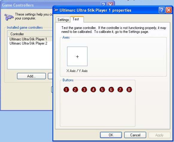
You can check in Control Panel, Gamepad Devices and each one should
show up as shown below:
Using
Custom Mappings
In analog mode, MAME (or other application) decides on how to interpret
analog joystick movements in games which do not require analog. But
think how much better it would be if the joystick could be programmed
to give YOU control over this! You could tell the joystick that it
should behave exactly like a 4-way stick, or an 8-way stick, or a 45
degree rotated 4-way stick (Q-Bert) or any other profile you wish! The
UltraStik does exactly this, and gives you total control of the
behaviour of the stick. The Ultrastik 360 does this by internally
overlaying a 9x9 matrix over the analog position information.
After you have created as many profiles as you wish, you can instruct
the stick to use the correct profile for the game by using the UltraMap
program on-the-fly to tell the stick which to use. There is no waiting,
the switchover is instant.
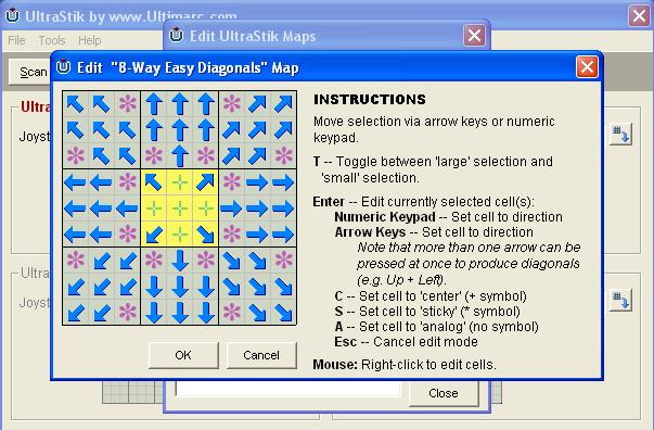
The full movement of the stick is pided into a matrix of 9X9 cells.
Note that in common with all analog sticks, the motion path of the
stick is circular so some squares are not accessible. You can define
every cell as one of the following types:
- Center: When moved to any of
these squares, the stick is centered
as far as the PC can see.
- Up, Left, Right, Down: These
directions can be selected to tell
the PC which direction to activate. Just like a switch-type stick.
- Diagonals: Four diagonal
locations can be selected. Just like a
switch-type 8-way stick
- Sticky: This tells the PC
that no change should be detected in
the location of the joystick. This type of square is usually defined in
between directions on a 4-way map to give some "hysterisis" or "play"
between the directions.
- Analog: This type of square
sends the analog position to the PC.
Obviously in a full analog mode, all squares in the matrix are defined
as analog.
You can combine any types of cell in a joystick map.
Using the UltraMap software, you can first define as many maps as you
wish and save them with appropriate names. Then select each as required
when you start a game. Mappings are held in Flash ROM in the joystick.
Note that the Flash ROM uses "block sparing" technology so that in the
unlikely event that a block of ROM fails to write, a spare, previously
unused block is brought into use. The last-used map is retained after
power-off.
Check out the programming page for full details of how to use the
UltraMap software.
Using
the special Mouse Pointer Map
One of the maps supplied with the UltraMap program is called "Mouse".
If you download this map, the joystick will be transformed into a mouse
pointing device Try it!
Use of
the 10-pin I/O port (Optional)
This 10-pin header can be used in two modes. The post auto-detects
which mode you are using. Note that on the U360F (Flight Stick) 3 of
the connector locations are already occupied. Additional wires can be
inserted into the free locations to connect another 6 buttons.
Input
Mode:
In this mode, you can connect 8
buttons to this connector, using the optional wiring harness. Each
button appears as a gamepad button on the PC. Each button is
independently de-bounced using a state-method for maximum roll-over
response. The 24Mhz CPU and high-speed USB 2.0 interface on the
Ultra-Stik 360 ensures top performance. Generally you would connect the
play buttons, plus start, for each respective player, to each UltraStik
360.
If you are using the special Mouse Pointer Map, buttons 1 to 3 become
mouse buttons (Left, Middle, Right).
Output
Mode:
In this mode, you can use the
optional wiring harness to connect 4 wires (plus ground and 5 volts) to
an I-PAC keyboard encoder. This allows the stick to behave exactly as a
switch-type joystick. It will activate the direction inputs on the
encoder to send keystrokes. Use of the USB connection is optional in
this mode, but you need to connect a 5 volt source if not using the USB
cable. You don't need to connect USB if you wish to replace a
switch-type stick with an UltraStik 360 and emulate the older stick.
You can't download maps of course without a USB connection so the stick
will behave as an 8-way joystick. In fact, in this mode, you can use
the Ultra-Stik 360 to replace any conventional joystick in any
application, including an original arcade machine.
The following table shows the behaviour in each of the two modes:
|
I/O
Port Connected to: |
USB
Data |
I/O
Port Data |
I/O
Port is used as Output.
USB not connected |
I-PAC,
J-PAC etc |
None |
4
Direction wires to emulate switches
Emulates 8-way stick |
I/O
Port is used as Output.
USB is connected |
I-PAC,
J-PAC etc |
Fully
Mappable Analog/Digital joystick
Cell matrix mappable to any 8-way direction, sticky
or center, or analog. |
4
Direction wires to emulate switches.
Responds according to the defined map (downloaded via USB).
Any analog cells are treated as center. |
| I/O
Port used as Input |
Buttons |
Fully
Mappable Analog/Digital joystick
Cell matrix mappable to any 8-way direction, sticky
or center, or analog. |
Input
from 8 buttons |
Note that when using in Output Mode, if you go into Control Panel,
Gamepad Devices, the 8 buttons will still be shown there, but they are
inoperative.
The connections for the 10-pin header are as below:
| Pin |
Wire |
Input
Mode |
Output
Mode |
| 2 |
Black |
COM
Connect to COM terminals on all buttons |
GND.
Connect to I-PAC if required |
| 3 |
Brown |
Button
1 NO |
not
used |
| 4 |
Red |
Button
2 NO |
Power
(5 volts) |
| 5 |
Orange |
Button
3 NO |
Right
Digital. Connect to I-PAC if required |
| 6 |
Yellow |
Button
4 NO |
Left
Digital. Connect to I-PAC if required |
| 7 |
Green |
Button
5 NO |
Up
Digital. Connect to I-PAC if required |
| 8 |
Blue |
Button
6 NO |
Down Digital. Connect to I-PAC if required |
| 9 |
Violet |
Button
7 NO |
Raw
analog. Requires special firmware |
| 10 |
Grey |
Button
8 NO |
Raw
analog. Requires special firmware |
The optional wiring harness has cut wire ends which you can crimp
suitable connectors onto, for your pushbuttons. There is one ground
wire which you will need to daisy-chain to all COM connections on the
switches so you may need additional black wire to do this.
Harness wiring is shown below:
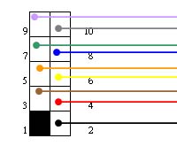
The supplied wires are 18 inches (450mm) long.
Customizing
the joystick (Excl U360F Flight Stick Version)
Restrictor Plates (Rear
Mounting)
Note that the rear-mounting restrictor plates are designed to be a
one-off fit, not
suitable for regular removal and refitting.
The
U360F (Flight Stik) version is not designed for use with any restrictors
as it is intended to be an analog stick.
We expect most people will find the UltraStik 360 to be perfect for all
gaming applications including analog and any variation of digital. But
we recognise that some people would prefer a different "feel" to the
stick with a mechanical limit on it's movement. So there are three
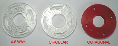
restrictor plates available.
4-8 Way restrictor:
This can be fitted in either 4-way or 8-way
mode and provides a mechanical limit for those people who prefer this.
You can easily adjust from 4 to 8-wy by turning the plate 45 degrees.
Round Restrictor:
For those who want to use the stick in full
analog and digital programmable mode, but prefer a stick with limited
mechanical movement, a round restrictor can be fitted.
Note that fitting the restrictors requires some dismantling so these
are a semi-permanent fixture.
Octagonal Restrictor:
This can be left in place and used in
either 4 or 8-way mode with no need to move the plate between each
mode. Octagonal restrictors are used on Sanwa joysticks and have a
great following.
To fit either restrictor:
Remove the 4 screws holding the PCB to the joystick body.
Remove the 4 screws securing the support brackets to the body. (you
will need a screwdriver which reaches through the holes in the top of
the brackets)
Place the restrictor plate over the holes and secure using the
silver-colored pillars. You can leave the 4-8 way restrictor free
enough to be turned by hand if you wish. You might need to use one of
the thumb-nuts to help turn the pillar.
Re-fit the PCB and secure with the four white thumb-nuts.
In the UltraMap software, go into "options" and tell the software which
type of restrictor is fitted.
You can see that, using the test feature in UltraMap, the stick
movement is still full-scale even though a restrictor is fitted.
Ultrastik With restrictor
fitted:
Front-Mount Restrictor Kit
This kit
is mounted on the top of the joystick before fitting to the panel. An
extra-long handle is supplied which needs to be fitted. Note the
easiest way of doing this is to remove the swivel assembly from the
front of the stick by removing the 4 screw on the faceplate. The E-ring
needs to be removed and the handle replaced..
Use of
maps when a restrictor is fitted
:
When using a restrictor plate, provided you have told the software you
have this fitted, a scale factor will be used which results in the
joystick being able to travel to the edge of the defined map matrix,
just as if there were no restrictor. But there will of course be cells
in the matrix which are not accessible and you need to be aware of this
when creating maps. You can test a map instantly using the test feature
in UltraMap.
Fitting
Long Handles and/or Replacement Spring (Not applicable to U360F):
There are two possible methods:
If your stick is not yet fitted to a panel, remove the 4 screws on the
front of the faceplate and remove the swivel assembly.
If your stick is already fitted to a panel, remove the PCB by
unscrewing the 4 screws.
Lift off the magnet assembly from the end of the shaft. Remove the
E-Ring.
CARE:
we advise to avoid spring-loaded parts being
lost, place a cloth over the joystick when removing the E-ring. Swap
the shafts and/or springs over and re-assemble.
Locking the threaded handle top.
If problems are experienced with the handle unscrewing, there is a
screwdriver slot available on the end of the shaft, to old the shaft
stationary while tightening the handle. This is accessible by removing
the PCB and the magnet assembly. After using this slot, check that no
burring of the end of the shaft has occurred, which might prevent the
magnet assembly from seating. Remove any burr using a fine file if
necessary.
LED
Indicator
The LED flashes to indicate correct operation. In the center of the
travel, the LED should flicker slightly. As the joystick is moved away
from center, each flash becomes longer. The axis which the LED
monitors, is changed when the stick is moved to full travel in each
axis.
Firmware Upgrade
The UltraMap software can be used to download new firmware to the
joystick. Firmware updates will be available for download.
Calibration
The UltraStik 360 requires no calibration. In Analog mode, the setting
of "dead zone" in MAME and also any calibration of gamepad joysticks in
Windows, will affect the stick, so if you get any strange behaviour,
check these are set to default settings.
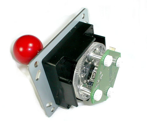
Magnet
Issues: Will my monitor be affected?
The UltraStik 360 contains a magnet (a Neodymium Iron Boron Radially
Polarised Magnet to be exact!). We have done extensive testing and have
found no problems with monitor screens being discoloured by the magnet
in the UltraStik, provided the joystick is mounted at a "normal"
distance from the screen in an upright cabinet. The only possible
exception might be in small cocktail tables where the joystick is
practically touching the monitor tube. We will be investigating a
shielded version for this case. Note that it is not possible to
permanently damage a monitor by the presence of a magnet.
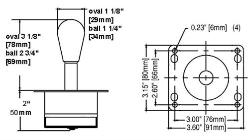
Mounting
Dimensions (Standard Version)
(Note that the optional
longer handles add 10mm to the shaft length)
Mounting
Dimensions (U360F Flight Stick Version)
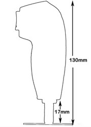
U360F
Flight Stik Version Installation Note
To install this version through the panel and the dust washer, the
handle needs to be dismantled. This is done by first removing 4 screws
from one side, then one from the other side.
The switches with wiring need to be routed through the panel and then
the handle re-assembled.
Shift
button
functionality
Button 8 is the shift button
This button has its normal function, unchanged
In addition to its normal function, when held down, it will activate
"virtual buttons" 9-15. Any other buttons pressed will register as 9-15
instead of 1-7.
In MAME you might wish to configure, for example, button 9 as "coin".
Then holding button 8 and pressing button 1 will generate the "coin"
signal.
You can test all button functions by going to Control Panel, Game
Controllers, Properties.
This firmware
does not contain any other chnages from 2.3 and if you do
not wish to have the shift function you can use 2.3 version.
Troubleshooting calibration problems (not centering)
The Ultrastik 360 self-calibrates but if there is some problem which
has put the offset too far out, this will fail.
To check, do the following:
First make sure that the device has not been calibrated in Windows. To
do this go to Control Panel, Game Controllers.
Click on the device and "Properties"
On the "settings" tab, click on "reset to default".
Make sure an analog map is downloaded to the stick
If the stick is still not centering correctly, check the LED.
First, switch the LED to the Y axis by moving full-travel up or down.
Then observe the LED. The flashes of the LED should be shortest when
the stick is centered in the up-down direction.
Then switch the LED to the X axis by moving full-travel left or right.
Again the flashes should be shortest in the center.
If the LED is not behaving correctly, this can be caused by bent PCB
mounting brackets or some other alignment problem.
Email
for assistance if
required.