Wiring Diagram.
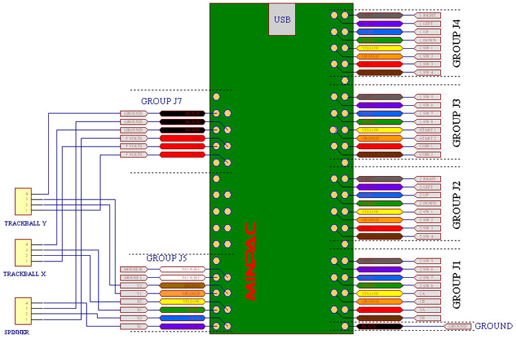
Arrange the large switch connector on your left with the wires running
towards the right, as shown in the right side of
the diagram above, with the white polarising key at the bottom.
Working from the
bottom of the connector, first
connect the BLACK wire to the male connector on the ground harness.
Separate the rest of the wires into 4 groups. Start each group with the
brown and red wires (bottom) and end with the purple and grey wires
(top). You can ty-wrap the 4 groups close to the connector if you wish,
or just lay the groups across the panel.
Now the wires from each group can be connected to the correct switches
as shown on the diagram above. The table below may help, as this
presents the connections in switch order and shows only the
commonly-used switches
Then connect the ground harness to the other contact of each switch.
Run along the controls in the most convenient path. You can miss out a
connector if you need a longer routing as there are spares. Cut off the
extra length.
If you are using the trackball/spinner harness connect the three other
plugs to the trackball and spinner as shown and connect this to the
board.
Ty-Wrap all wiring for neatness.
Reversing Trackball Axis
If you find one of the trackball axes moves "backwards", the resolution
is to swap the X1 and X2 wires over (or Y1
and Y2). To do this,
consult the diagram above and locate the correct pair of wires, at the
main 30 way plug. The wire and contact can be removed from the black
housing by carefully lifting the small tab on the side of the housing
and pulling out. Swapping the pair of wires will reverse the direction
of that axis.
Connecting Mouse Buttons
Mouse buttons can be connected to the trackball/spinner harness
connector. These are not fitted as standard. They should be located as
shown in the diagram above. You can swap over two spare wires
from
your switch harness. The wire and contact can be removed from
the
black
housing by carefully lifting the small tab on the side of the housing
and pulling out. Alternatively use two wires from the optional
extension wire pack.
Keycodes, Programming and
other Information.
All of the information on the I-PAC applies to the Mini-PAC. The
default keycodes are the same, all programming
information applies
inclusing use of the WinIPAC utility, so
check out the I-PAC pages for further information.
Troubleshooting Tips
All of the information on the I-PAC applies to the Mini-PAC. The LED
indications are the same, all troubleshooting information applies, so
check out the I-PAC pages for further information.